Electronics
Circuit boards, from schematic to a unit that powers up.
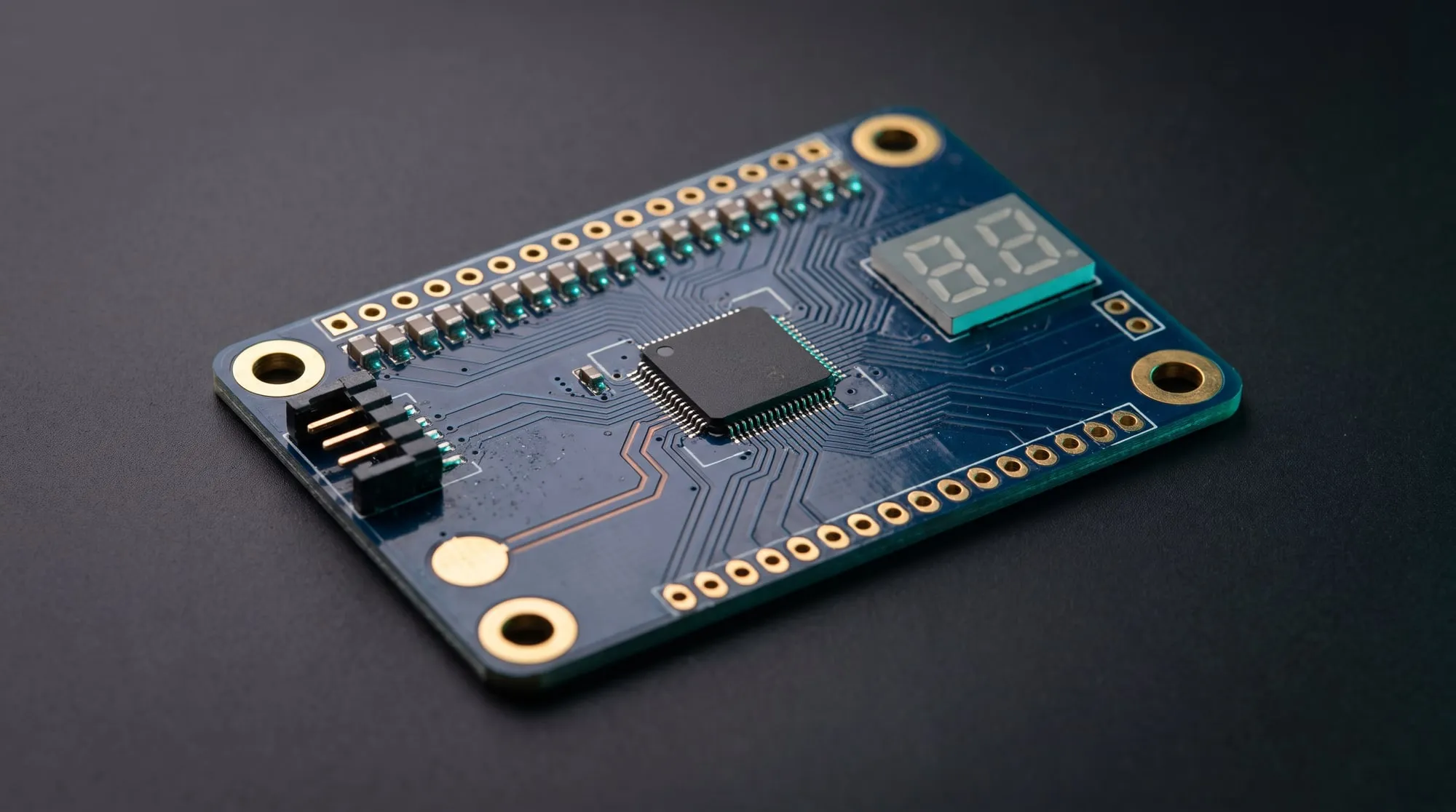
Board design for product companies: schematic capture, layout, fabrication files and bring-up, with the firmware and the enclosure fit worked out alongside so the first assembled unit behaves.
- Scope
- Schematic, layout, fabrication files, bring-up
- Strengths
- High-speed digital, RF, pulsed power
- Mechanical
- Enclosure fit checked in SolidWorks
- Pricing
- Fixed quote per board or per milestone
- Samples
- Shared privately on request
What I take on
Five years of board design in industry before opening this studio. I work alone, so I take a small number of boards at a time and stay on them until they work.
- A new board from requirements
- Architecture, part selection, schematic, layout and the full manufacturing package.
- Layout from your schematic
- You have the circuit. I place and route it, with the stack-up and constraints written down.
- Design review
- A second pair of eyes before you pay for fabrication. Written findings, ranked by risk.
- Bring-up and debug
- First power-on, a test plan, and patient work on the board that almost works.
- Revision for manufacture or cost
- Taking a working prototype and making it cheaper, easier to assemble or easier to source.
Three areas I know from the inside.
The figures below are working models, not illustrations. Move the controls. They are the first calculations I would run on your project.
High-speed digital and fiber-optic links
Getting bits across a board and down a fibre without losing them. That is controlled impedance, matched lengths, unbroken return paths, clean reference clocks and quiet power for the transceiver.
An eye diagram is the verdict on all of it. When the channel is short of bandwidth or the clock jitters, the eye closes and errors follow.
- Eye height
- –
- Eye width
- –
- Eye
- –
RF links
A radio link either has margin or it has excuses. I start with the budget, then protect it in the layout: matching, filtering, the antenna feed, shielding and the ground underneath.
Double the distance and you lose 6 dB. The model shows how quickly margin disappears, and what an antenna buys back.
- Path loss
- –
- Received
- –
- Margin
- –
- Link
- –
Pulsed power: drive and measurement
Delivering thousands of amps for a few microseconds is a layout problem before it is a circuit problem. Loop inductance sets the peak current and the rise time, and it is decided by where the copper goes.
Measuring a pulse like that is its own discipline: sensor bandwidth, grounding and isolation, so the trace on the screen is the current and not the noise.
- Peak current
- –
- Time to peak
- –
- Stored energy
- –
- Response
- –
What you receive
Everything needed to build the board without me, and to change it later. Native files are always included.
| Deliverable | Contents |
|---|---|
| Schematics | PDF for review, plus the native project files |
| Layout | Native board files with the stack-up, impedance targets and design rules recorded |
| Fabrication outputs | Gerber or ODB++, drill files and a fabrication drawing |
| Assembly outputs | Bill of materials with manufacturer part numbers, pick-and-place file and assembly drawing |
| 3D model | STEP file of the populated board for your mechanical designer |
| Bring-up notes | What was tested, what was measured, and anything still open |
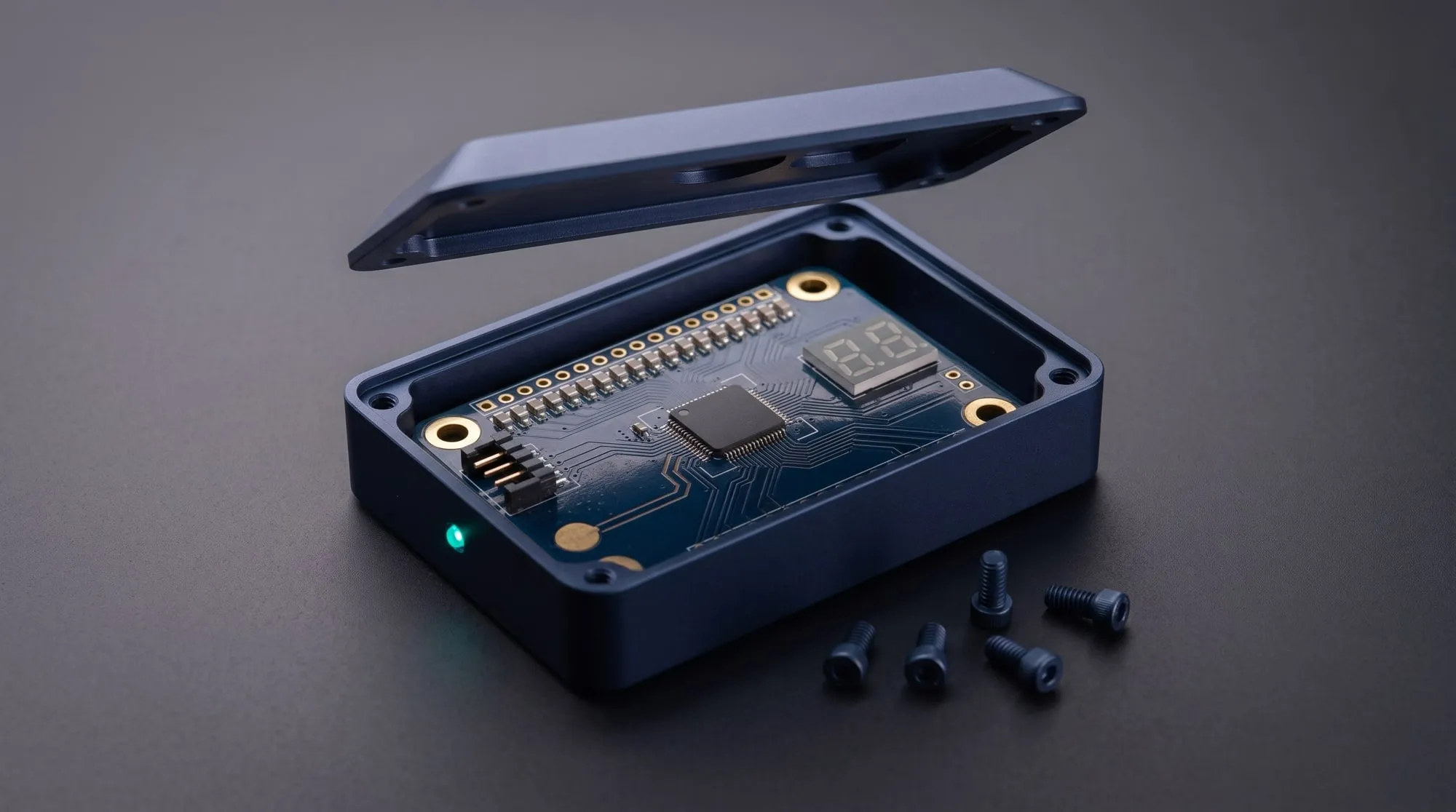
The board has to fit the box.
Most first-build surprises are mechanical. A connector sits half a millimetre proud, a tall capacitor meets a rib, the mounting holes are right on the drawing and wrong in the hand.
I work the board and the enclosure together in SolidWorks: outline, connector positions, mounting, keep-outs and height limits, checked in 3D before anything is ordered. If you have a mechanical designer, we trade STEP files until both sides agree.
- Board outline and mounting
- Derived from the enclosure, not guessed at.
- Connectors and cut-outs
- Aligned to the wall they pass through, with tolerance.
- Clearance and height
- Every tall part checked against the lid and its neighbours.
- Thermal and service access
- Heat has a path out, and the test points can be reached.
How a board project runs
Five milestones, each with something for you to approve before the next begins.
-
Requirements
What the board must do, the constraints, and an architecture with the key parts chosen.
You approve Requirements and block diagram
-
Schematic
The full circuit, with calculations for the parts that matter.
You approve Schematic review
-
Layout
Placement first, then routing, with the enclosure open alongside.
You approve Placement, then the final layout
-
Release
The manufacturing package, checked against the fabricator’s rules.
You approve The order to fabrication
-
Bring-up
First power-on, test plan, measurements and fixes.
You approve Acceptance against the requirements
Each milestone is quoted and invoiced on its own, so you can stop, pause or change direction at any review.
Questions about board work
Can you start from a rough idea, or do I need a specification?
Either. If you have a specification, I work to it and flag anything that looks risky. If you have an idea and a list of what the product must do, the first milestone is turning that into requirements and an architecture we both sign off.
Will you review a board someone else designed?
Yes. A design review before fabrication is one of the most useful things I do, and the cheapest. You get a written list of findings ranked by risk, each with a suggested fix.
Who owns the design files?
You do, once the milestone is paid. You receive the native source files as well as the manufacturing outputs, so you are never dependent on me to make a change.
Do you handle manufacturing?
I prepare everything a fabricator and an assembler need, answer their engineering questions, and help you choose a supplier. You place the orders, so the supplier relationship and the pricing are yours.
What about FCC, UL or CE testing?
Compliance testing is done by accredited labs. I design with those tests in mind, prepare the technical information the lab asks for, and help work through any failures.
Can you sign an NDA?
Yes, and I expect to. Send yours, or I can send a mutual one. Nothing about your project is discussed or shown elsewhere.
Bloomquist Design provides design services for product development. I am not a licensed Professional Engineer and do not take on work that requires a PE stamp, such as building electrical systems.
Tell me about the board.
A paragraph on what it has to do is enough to start. I can sign an NDA first if you prefer.